Turbocharged engines power millions of cars worldwide, from daily commuters to high-performance sports cars. These remarkable devices squeeze more power from smaller engines while improving fuel efficiency. But how exactly do turbos work their magic under the hood?
A turbocharger uses exhaust gases to spin a turbine that forces more air into the engine. This process creates a continuous cycle that dramatically increases engine power output without requiring a larger displacement. The technology transforms otherwise wasted exhaust energy into usable performance gains.
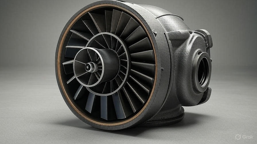
The Basic Turbo System Components
Every turbocharger system contains several key components that work together seamlessly. The turbine housing contains the hot-side turbine wheel, which captures energy from exhaust gases flowing out of the engine. Exhaust gases spin this wheel at incredibly high speeds, often exceeding 200,000 RPM in modern applications.
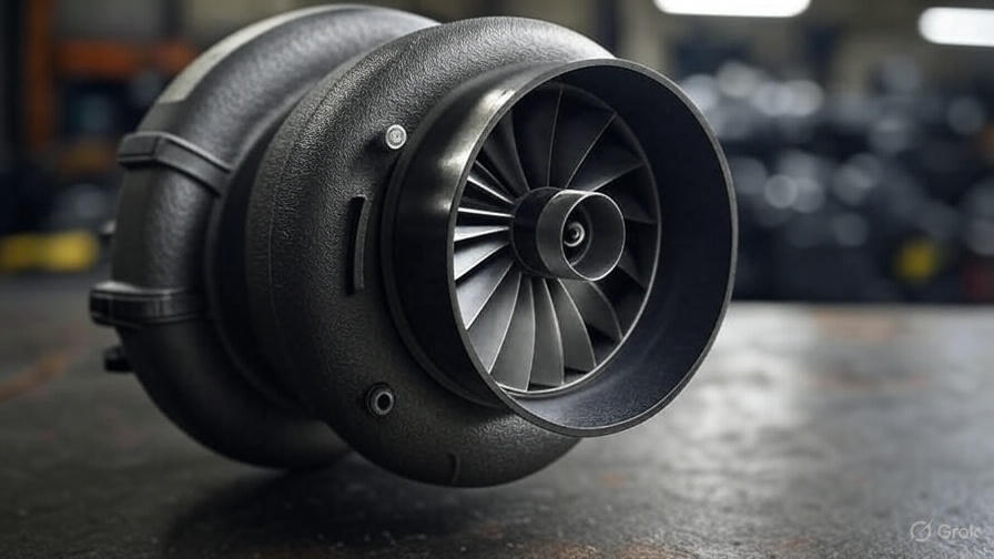
Connected directly to the turbine wheel sits the compressor wheel, housed in the cold-side compressor housing. This wheel draws ambient air through the air filter and compresses it before sending it to the engine’s intake manifold. The connection between these two wheels occurs through a precision-balanced shaft that must withstand extreme temperatures and rotational forces.
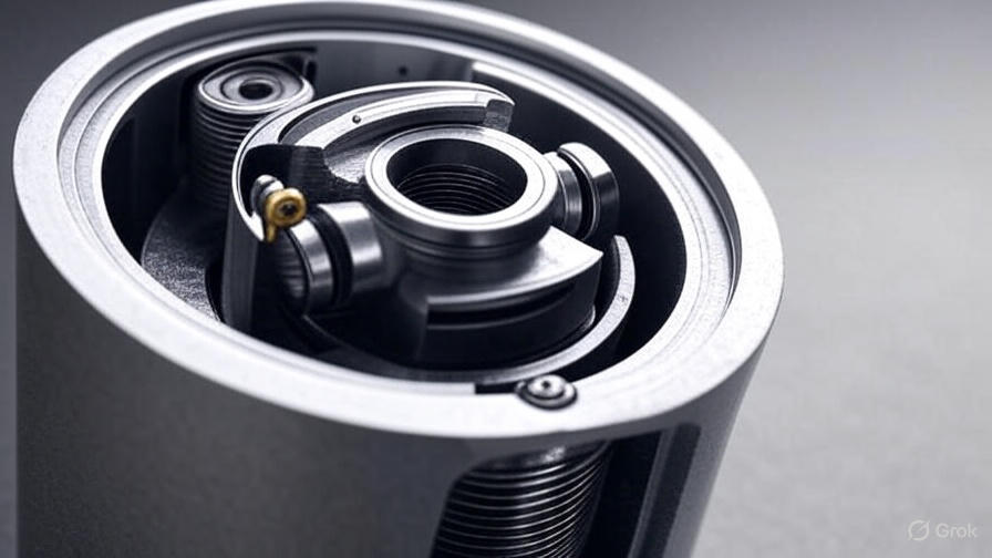
The center housing, also called the bearing housing, contains the shaft bearings and lubrication system. This critical component keeps the spinning assembly properly aligned while managing heat transfer between the hot turbine side and cooler compressor side. Oil flows through passages in this housing to lubricate bearings and carry away heat generated by the high-speed rotation.
Wastegate systems control boost pressure by allowing some exhaust gases to bypass the turbine wheel when target pressure levels are reached. Internal wastegates integrate directly into the turbine housing, while external wastegates mount separately with dedicated piping. Both designs prevent overboosting that could damage engine components.
Exhaust Energy Conversion Process
Engines naturally produce exhaust gases as a byproduct of combustion. These hot gases contain significant kinetic energy that normally exits through the tailpipe unused. Turbochargers capture this energy by positioning the turbine wheel directly in the exhaust flow path.
Hot exhaust gases strike the curved blades of the turbine wheel, causing it to spin rapidly. The turbine housing’s volute design channels exhaust flow efficiently around the wheel’s circumference, maximizing energy transfer. As gases expand and cool while passing through the turbine, they give up their energy to create rotational motion.
The turbine wheel’s design optimizes energy extraction across different engine operating conditions. Blade angles, wheel diameter, and housing geometry all influence how effectively the system converts exhaust energy into shaft rotation. Engineers carefully balance these factors to match turbocharger response characteristics with specific engine requirements.
Exhaust backpressure naturally increases when a turbocharger restricts exhaust flow. However, the power gains from forced induction typically far outweigh the small efficiency losses from increased backpressure. Modern turbine designs minimize flow restrictions while maximizing energy extraction.
Air Compression and Intake Boost
The compressor side transforms the turbine’s rotational energy into pressurized intake air. As the compressor wheel spins, its curved blades accelerate ambient air radially outward through centrifugal force. This acceleration increases the air’s velocity and pressure significantly.
The compressor housing’s diffuser section converts high-velocity air into high-pressure, lower-velocity air suitable for engine intake. Carefully designed passages gradually slow the airflow while maintaining pressure gains. This process ensures stable, consistent airflow to the engine across various operating conditions.
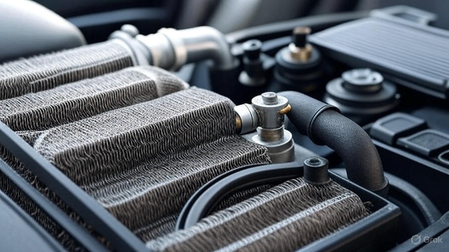
Compressed air becomes significantly hotter due to the compression process itself. This temperature increase reduces air density, partially offsetting the pressure gains. Intercoolers address this issue by cooling the compressed air before it enters the engine, maximizing the density benefits of turbocharging.
Boost pressure typically ranges from 5 to 20 PSI above atmospheric pressure in most applications. Higher boost levels create more power but also increase stress on engine components. Boost controllers and wastegates maintain optimal pressure levels while preventing harmful overboosting scenarios.
The Continuous Cycle Operation
Turbocharger operation creates a self-reinforcing cycle that builds upon itself. Initial engine load increases exhaust gas flow and temperature, spinning the turbine faster. Increased turbine speed drives the compressor harder, creating more boost pressure for the engine.
Higher boost pressure allows more fuel injection, creating larger combustion events that produce more exhaust energy. This additional exhaust energy spins the turbine even faster, creating a positive feedback loop. The system reaches equilibrium when wastegate control limits further boost increases.
Engine load changes directly affect turbocharger response. Light throttle applications produce minimal exhaust energy, resulting in little to no boost pressure. Full throttle operation generates maximum exhaust flow, allowing the turbocharger to reach its full potential quickly.
The continuous nature of this cycle means turbochargers respond proportionally to driving demands. Gradual acceleration produces gentle boost buildup, while aggressive throttle inputs create rapid boost response. This characteristic makes turbocharged engines feel responsive and flexible across different driving styles.
Turbo Lag and Spool-Up Time
Turbo lag describes the delay between throttle input and boost pressure buildup. This phenomenon occurs because the turbine wheel must accelerate from low speeds to effective operating RPM before generating meaningful boost pressure. Larger turbochargers typically exhibit more lag due to their increased rotational inertia.
Several factors influence spool-up characteristics. Turbine and compressor wheel sizes directly affect rotational mass and acceleration rates. Smaller wheels spin up faster but may limit peak power output. Larger wheels provide more top-end power but require more time to reach operating speed.
Exhaust manifold design significantly impacts turbo response. Short, equal-length runners preserve exhaust pulse energy and improve low-end response. Log-style manifolds may reduce manufacturing costs but often compromise spool-up performance compared to optimized designs.
Modern turbocharger technology has dramatically reduced lag times through advanced materials and design techniques. Lightweight titanium aluminide turbine wheels, precision ball bearings, and optimized aerodynamics help contemporary turbos respond much faster than older designs.
Heat Management and Cooling
Turbochargers operate in extremely harsh thermal environments. Exhaust gases can reach temperatures exceeding 1800°F, while the compressor side generates additional heat through air compression. Effective heat management prevents component damage and maintains consistent performance.
The center housing uses engine oil circulation for cooling and lubrication. Hot oil carries heat away from critical bearing surfaces while providing necessary lubrication for the high-speed rotating assembly. Oil supply pressure and flow rates must meet manufacturer specifications for reliable operation.
Heat barriers between the turbine and compressor sides minimize heat transfer that could damage compressor components. Thermal barrier coatings on turbine housings reflect heat away from surrounding components. These coatings also help maintain exhaust gas temperatures for improved turbine efficiency.
Water-cooled center housings provide additional cooling capacity in demanding applications. Coolant circulation removes more heat than oil alone, enabling higher performance levels while maintaining component durability. This cooling method is particularly common in diesel and high-performance gasoline applications.
Different Types of Turbocharger Systems
Single turbocharger systems represent the most common configuration. One turbocharger handles all exhaust flow from the engine, providing boost across the entire RPM range. These systems offer simplicity, lower cost, and easier maintenance compared to more complex arrangements.
Twin-turbo setups use two smaller turbochargers instead of one large unit. Parallel twin-turbo systems split exhaust flow between two identical turbochargers, reducing individual unit stress while maintaining quick response. Sequential twin-turbo systems use a small turbo for low-end response and a larger unit for high-RPM power.
Variable geometry turbochargers adjust their internal geometry to optimize performance across different engine speeds. Movable vanes in the turbine housing alter exhaust gas flow angles and velocities. This technology provides excellent low-end response while maintaining high-RPM performance capabilities.
Electric turbochargers use electric motors to eliminate lag completely. These systems can provide instant boost independent of exhaust gas flow. However, electrical power requirements and system complexity currently limit their adoption to high-end applications and hybrid powertrains.
Maintenance and Longevity Factors
Proper maintenance extends turbocharger life significantly. Regular oil changes with high-quality synthetic oil prevent bearing damage and carbon buildup. Oil change intervals should follow manufacturer recommendations, often more frequent than naturally aspirated engines require.
Heat cycles create the most stress on turbocharger components. Allowing the engine to idle briefly after hard driving lets the turbo cool gradually rather than experiencing thermal shock. This practice prevents bearing damage and extends overall turbocharger lifespan.
Air filter maintenance becomes critical in turbocharged applications. Dirty air filters increase compressor work and can allow contaminants to damage compressor wheels. Premium air filters designed for forced induction applications provide better protection and flow characteristics.
Fuel quality directly affects turbocharger durability. Poor-quality fuel creates carbon deposits that can damage turbine wheels and clog oil passages. Premium fuels with detergent packages help keep the system clean and operating efficiently.
Performance Benefits and Applications
Turbochargers enable significant power increases without increasing engine displacement. A well-designed turbo system can increase power output by 30-50% or more compared to the same naturally aspirated engine. This efficiency allows smaller engines to produce power levels previously requiring much larger displacement.
Fuel economy improvements represent another major benefit. Smaller turbocharged engines consume less fuel during light-load conditions while providing adequate power when needed. This combination of efficiency and performance has driven widespread turbocharger adoption across the automotive industry.
Emissions benefits result from improved combustion efficiency and reduced engine displacement. Smaller engines produce fewer emissions during typical driving conditions. Precise boost control also enables optimized air-fuel ratios that minimize harmful emissions while maximizing performance.
High-altitude performance improvements make turbochargers valuable for aviation and mountain driving applications. As atmospheric pressure decreases with altitude, naturally aspirated engines lose power rapidly. Turbochargers can maintain sea-level power output even at significant elevations.
Modern Turbocharger Technology Advances
Advanced materials have revolutionized turbocharger capabilities. Titanium aluminide turbine wheels withstand higher temperatures while weighing less than traditional materials. These improvements enable faster spool-up and higher performance levels with improved durability.
Precision bearing systems reduce friction and improve response characteristics. Ball bearings replace traditional journal bearings in many applications, reducing rotational drag and enabling faster acceleration. Some systems use magnetic bearings that eliminate physical contact entirely.
Electronic boost control provides precise pressure management across all operating conditions. Electronic wastegate actuators respond faster and more accurately than pneumatic systems. Integration with engine management systems enables sophisticated boost control strategies that optimize performance and protect components.
Aerodynamic improvements in wheel and housing design maximize efficiency while minimizing size requirements. Computational fluid dynamics allows engineers to optimize gas flow paths for specific applications. These improvements result in better response, higher efficiency, and reduced packaging requirements.
The future of turbocharger technology continues evolving rapidly. Electric assistance, advanced materials, and intelligent control systems promise even better performance and efficiency. As emissions regulations tighten and efficiency demands increase, turbochargers will remain essential tools for meeting these challenges while delivering the performance drivers expect.